| | |
Adding a rear stabilizer bar to a Dodge Caravan
According to the factory service manual, some of the Caravan models came with a rear stabilizer bar. However, I've never actually seen any Caravans (or Voyagers or Town & Countries) with rear stabilizer bars in the pull it yourself parts yard's I've checked. I've been looking for one for several months and haven't found one yet. They seem to be pretty rare.
Since I can't seem to find a factory unit, and I really want a rear stabilizer bar to reduce body roll and reduce understeer handling in our van, I decided to expand my criteria a little bit and search for a bar that I could make fit.
On vehicles with a solid rear axle, like the Chrysler Corporation minivans, there are two ways to mount the rear stabilizer bar. The stock bar is mounted to the axle beam and the end links are attached to the body. There are some disadvantages to this arrangement. The weight of the stabilizer bar is completely unsprung this way. However, it is easy to mount it up that way, and that's what Chrysler Corporation chose for their implementation.
Since I'm doing my own engineering here using other parts, I thought I'd try the other alternative. I want to mount the stabilizer bar to the body if possible, and connect the end links to the axle near the wheels. This has an advantage that it keeps the main (heaviest) part of the stabilzer bar on the body where it's sprung weight. This places less of a load on the shocks and springs and can result in better handling than having the additional unsprung weight of the bar on the axle.
I got under our van and looked around the back, behind the rear axle. There's a lot of room back there, and there's some extra bolt holes already prepared in the frame rails on the unibody. Those holes might be useful to mount the stabilizer bar to the body. On the suspension end of thing, out by the wheel, it looks like it wouldn't be too much trouble to stack some kind of bracket on top of the leaf spring, under the U-bolts, to secure the endlinks of a stabilizer bar to the suspension there.
So, I drew this little diagram outlining the requirements for a rear stablizer bar mounted on the body with end links on the axle.
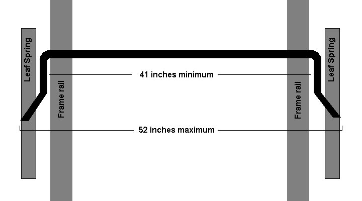
Figure 1 - Plan for rear stabilizer bar
Click on the diagram for a larger version.
I guess this would be a good time to talk a little bit about stabilizer bars, or anti-sway bars, as they are sometimes called.
All stabilizer bars work about the same. They are like a torsion bar, but both ends are attached to the end of the axle or suspension near the wheels. Instead of supporting the weight of the chasis, they transfer weight from one side to the other in cornering.
The amount of weight transferred during cornering, and the ability of the bar to reduce roll and keep the vehicle level during cornering depends on the stiffness of the bar. The stiffness is related to three different characteristics of the bar.
- Thickness - The thicker the bar, the stiffer it will be. Thinner bars are less stiff.
- Length - The length of the straight(er) part of the bar affects stiffness. If two bars are the same thickness, the one that is shorter between the body mounting bushings will be stiffer. Shorter is stiffer, longer is less stiff.
- Lever arm length - The distance from where the end link attaches to the center of the bar where it mounts to the body affects the stiffness of the bar. Shorter arms here make for a stiffer bar. Longer arms ar less stiff. Basically, this affects how much leverage the wheels and suspension parts have on the bar. There's a limit to how short the arms can be, too. If they are too short for the suspension travel, the ends will have a lot of front to rear motion in addition to the up and down motion of the suspension. About 8 inches is the shortest arms I've seen on a stabilizer bar designed for street use.
So, now we know the dimensions that are critical for the Caravan, and we know the factors that affect the stiffness of stabilizer bars. We want to go find a suitable bar at the used parts yard now. Since the van is fairly heavy, and since it seems to have a whole lot of understeer designed in in stock form, I'm looking for a relatively stiff bar. We'll see what I can find today.
Well, I got to the yard, and I thought I'd look at bigger rear wheel drive cars first. I was hoping to find a front bar from one of these that would fit. Front engine, rear wheel drive cars tend to have large, thick, fairly stiff front stabilizer bars. Unfortunately, front stabilizer bars on any vehicle have to be fitted to clear the wheels at full lock steering angles. Even the big mid 1970's Cadillac Fleetwoods and full sized vans and pickups only had about 36 to 38 inches of straight bar in the center between the bends. This won't clear the frame rails on the Caravan. The end links on these big cars were usually close to 48 inches apart. A bar with those dimensions would be guaranteed to interfere with the frame rail on the caravan. So these were unusable for me.
So, I was probably going to have use a rear stabilizer bar from something. There weren't too many available that would fit the dimensions required. I did find a few different potential donors, though.
I finally ended up pulling a rear stabilizer bar from a late 1980's model Toyota van and taking it up to the Chrysler section of the yard. I figured I'd put it under a minivan there in the yard and get a quick look at what I was dealing with.
 | | Photo 1 - Rear stabilizer bar from a Toyota van |
Well, it looked like it was going to be a good fit. It was about 3/4" (18 mm) in diamter, and right around 42 inches between the arms at the end. The arms were bent at almost a 90 degree angle. It looked a whole lot like my diagram, but the last bit at the end was even straighter than my drawing. Photo 1 is a picture of the Toyota van rear stabilizer bar.
So, I took that one home with me for only $15.
On the way home, I stopped at an auto parts place. The donor Toyota van was missing the whole rear axle. Whoever pulled the axle had removed the nuts and rubber bushings from the end links. The end links were still attached to the end of the stabilzer bar, but the end that attaches to the axle was just a threaded rod with no nut and no bushings.
I asked at the parts place for the end link bushings. The parts place could order the bushings, but they were a special order and would take 10 to 15 business days to arrive. So, I was off to see if the Toyota dealer could do any better. The end link bushing kits were only going to be around $5 per side from the parts place, so a dealer probably couldn't be too bad for the parts.
Here's a tip for all of us junk yard shoppers. If you take parts off of a strange vehicle (from a make or model that you don't actually own), write down the VIN # of the donor. When I got to the Toyota dealer's parts counter, they wanted to know the year, model, engine, transmission (automatic or manual) and some other information about "my" van. If you don't have that information, it's hard for them to look up the additional parts you might need (or replacement parts if rubber bits wear out down the road). Usually, if you say, "look, I don't know much about the thing, but here's the VIN number," they can get the info they need by decoding the VIN #.
The Toyota dealer also was going to have to order these bushings. Each bushing and keeper washer was less than $2, but there were 6 on each side, plus the rubber bushings in the bar where the endlink attaches to the bar. So it was going to be about $25 for everything. The parts took a few days to arrive, but once they were in, I was set. When installing mine, I found that I didn't actually need the center metal washer/keeper piece. The rubber bushings fit snug into the 1/2 inch hole in my flat bracket. I'm guessing that that keeper must be used on the Toyota where the surface the bushing is against isn't flat.
In the mean time, I mounted the thing on our van and fabricated the brackets to make it work.
First, I need to get the thing mounted to the body of the van. On our van, there were 4 holes on each frame rail that were conveniently located for this. They already had captive nuts in them, so I just had to find some bolts to thread in the holes. A M8x1.25 bolt seemed to be the best fit, though there was a little bit of surface rust and even that bolt didn't thread in the best. If I had a tap for that size, it would have been a good idea to run the tap through the hole to clean it up. I didn't have the right tap, so I just coated the bolts with antisieze/lubricant and did the best I could.
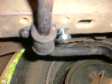 | | Photo 2 - Rear stabilizer bar mounting bracket (temporary) |
The brackets from the Toyota had a hole for a bolt at one end and a tab that went in a slot on the Toyota's frame on the other end. I considered making a bracket of my own out of some steel flat stock. But just to get it mounted, I put those brackets up with the bolt hole at the rear. I snugged a couple of bolts in the holes and pulled everything up snug. Then, I used a big washer on the bolt at the front to hold the little tab up. Actually, looking at this, I might just run with it that way. I did put a washer that I had cut to match the tab in as well. Photo 2 is a picture of the bracket being mounted on the driver's side. After installing this, I decided that it was probably good enough for now. I still might make some brackets specifically for this bar on our van, but the Toyota bracket held down by large washers at the front seems to be doing well. I'm going with the "don't fix it if it ain't broke" approach right now.
So, with the bar mounted to the body of the van, the next step is to attach the end links to the suspension at the wheels. In order to do this, I'll need a bracket that attaches to the leaf spring and has a hole in it for the end link to go through. I drew up this little diagram to show what I needed.
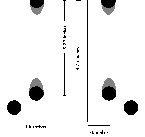
Figure 2 - Bracket to attach end link to the leaf spring/axle.
Again, click on the diagram for a larger version.
A couple of notes here. First, the brackets I made were slightly different from the diagram. I adjusted the diagram a little bit based on the clearances and angles I saw after installing my first version brackets. The diagram was updated to reflect this experience and will fit better than what I actually made.
The second thing is that if I had this project to do again, I'd seriously consider making the bracket out of 3/16" or 1/4" channel stock and using straight grade 5 or grade 8 bolts instead of the U-bolt. The bracket would have to be slightly longer in order to have a full hole on the outer end instead of the notch on mine. But this would avoid buying an overpriced U-bolt from the dealer, and I don't think grade 5 bolts on a channel stock bracket would be any weaker than the factory U-bolts. It might actually be stronger than the factory U-bolt, and the hardware and stock are easier to find and less expensive than the U-bolt.
Third, measure your U-bolts and make sure that what you are making will fit your car. When I first posted this page, I had a mistake on the bracket plan above. I've updated the pan now to show what I believe are correct dimensions, at least for our van. Don't assume my drawing will fit your minivan.
I used 1/8" by 2" cold rolled steel flat stock for mine. I'd recommend cold rolled stock rather than hot rolled because this part will have some stress on it in normal use. Also, it's much easier to prepare and paint cold rolled stock than hot rolled. With hot rolled stock, you have to sand/grind off the mill scale and surface rust first. I cut two pieces of flat stock, 4 1/2" long, and I drilled the holes necessary for the U-bolts and end links.
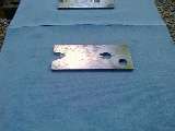 | | Photo 3 - End link bracket before painting. |
Here's one of my brackets after cutting and grinding. You can see that I ground out around the holes where the U-bolt will go to give the bolt clearance, and to prevent sharp, hard edges from cutting into the U-bolt. I used an air powered die grinder on mine, but you could use a dremel tool or even a hand file to do this work. I painted my brackets so they wouldn't rust out or cause rust problems on the springs. Rustoleum or similar "rust proofing" paints take a very long time to dry. If you do this, allow a day or two (or maybe even a couple of weeks) for the thing to dry out. I scratched mine a little while I was installing them, mostly because the paint was still tacky even after two or three days.
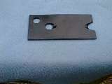 | | Photo 4 - End link bracket painted and ready to install. |
Now, it's time to install the brackets on the van. If you're going to use the stock U-bolts, get two replacements from the stealership. Don't bother buying the nuts there, they probably don't have them and will have to backorder them. They'll also want $4.00 or more per nut. Go to a good hardware store and buy Grade 8 or even Grade 5 nuts, 1/2" fine thread (UNF). Get some hardened, plated washers while you are at the hardware store, too.
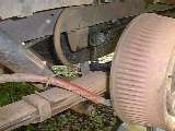 | | Photo 4 - End link bracket installed and hooked up. |
Installing and hooking up the first one is easy. Just put the bracket on top of the leaf spring, under the U-bolt. Actually, installing it is pretty easy, but getting the U-bolt off can be very difficult. The nuts tend to rust onto the U-bolts, and even when you get them turning, they tend to strip the threads on both the nuts and the U-bolts. Put lots of penetrating oil on the U-bolt the night before you try to do this. It also helps if you have a long breaker bar or an air powered ratchet to turn the nuts once they strip out. I've taken eight of these U-bolts off of these vans, and only one came off without stripping at least one of the nuts. Have replacement parts when you do this, and use the new ones even if you manage to get the originals off without stripping the threads. These threads are pretty highly stressed, and if it didn't strip this time, it probably will when you're putting it back together. Using new hardware minimizes the risk of that.
Tighten the nuts on the U-bolts to 65 foot pounds with a torque wrench. It will feel funny, almost like you're stripping the threads on the bolt. You're actually compressing the leaves of the spring together, so, it will take a lot of turns of the nut after it's snugged down to get to the 65 foot pound torque spec. I felt a lot better when I set the wrench to 35 pounds first. Then, after tightening to that, I stepped it up to 50 foot pounds, and then finally up to the final spec of 65 foot pounds.
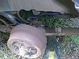 | | Photo 5 - Second end link bracket being installed. Note the jackstand used to push the axle/leaf spring into position to allow the endlink nut to be installed. |
The second one is a little more difficult. Once you have the bracket installed and the nuts on the U-bolt torqued properly, you'll have to connect the endlink and put the nut on it. If you have the van jacked up, the suspension will be unloaded on this side, the bar will be up fairly high and the threaded part won't reach through the hole in the bracket. The easiest solution to this is to put a jackstand under the axle or under the leaf spring just behind the axle and lower the van onto the jackstand to load up the spring and the suspension. See photo 5 for a picture of how I did this on mine.
The van can be driven at this point. Of course, you dropped the spare tire to make room to put the bar in, and now there's a bar across the spare tire area. I'm not sure what the long term solution to this is. I found that the spare tire will pull up snug against the bar. I just wrapped my bar in pipe insulation to prevent any rotation of the bar from wearing on the sidewall of the spare. I'm not sure how that will hold up for the long term. If it doesn't hold up, I'll make another cross piece from some aluminum tubing for the spare tire to rest against and to protect the moving bar from the fixed spare tire.
 | | Photo 6 - Spare tire installed against the stabilizer bar. |
So, now that it's mounted, and the spare tire is back (close to) where it belongs, it's time to drive with the new stabilizer bar on. I was impressed the first time I drove the thing with the new bar installed. It is much more level in corners, and a lot of the understeer characteristics of the handling have been tamed. If you push it hard, it still understeers a little. But in everyday driving, it feels much more neutral than it used to.
The final verdict is in. I just came back from a trip up to visit some friends in Tennessee. I drove the van on U.S. 64 from Ducktown to Cleveland Tennessee, along the Ocoee river. On the way home, I followed Tennesse route 68 from Sweetwater to Ducktown. These are really fun, curvy, mountain roads. These are the kind of roads where I really enjoy driving our Miata. But for this trip, I needed the carrying capacity of the minivan. The van handled very well on these roads. It's not the Miata, but it was much better than I remember it on these roads in the past.
Also, while I was in northern Tennesse, near Norris Lake, I was following a VW Passat. The Passat was having fun on this twisty section of U.S. 441 near Norris Dam. I'm sure he was wondering why he couldn't seem to pull away from that Dodge Caravan that was following about 10 seconds behind him.
This page has been viewed 1304 times
|